Air Compressor System Diagram
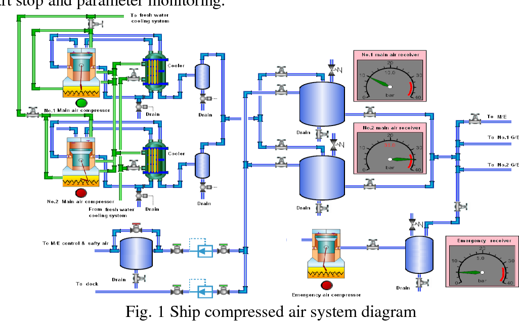
Air compressor system diagram. Fluid Power Equipment containing 113 elements of motors pumps. Of the air compressor and draw a piping diagram showing all fittings pipes joints valves etc. To understand the operation of an air compressor let us assume the cycle and indicator diagram for a simple single stage reciprocating air compressor as shown below.
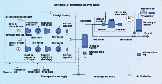
The figure shows the complete layout of the Air Brake System. Figure-1 depicts a typical process flow diagram PFD for instrument air supply system. Operator Manual Atlas Copco Gx5 Air Compressor Tommy Car Wash Systems.
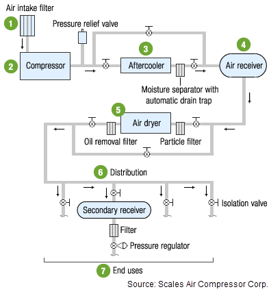
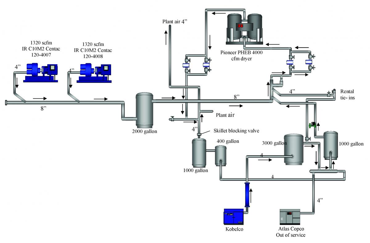
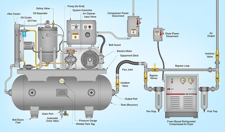
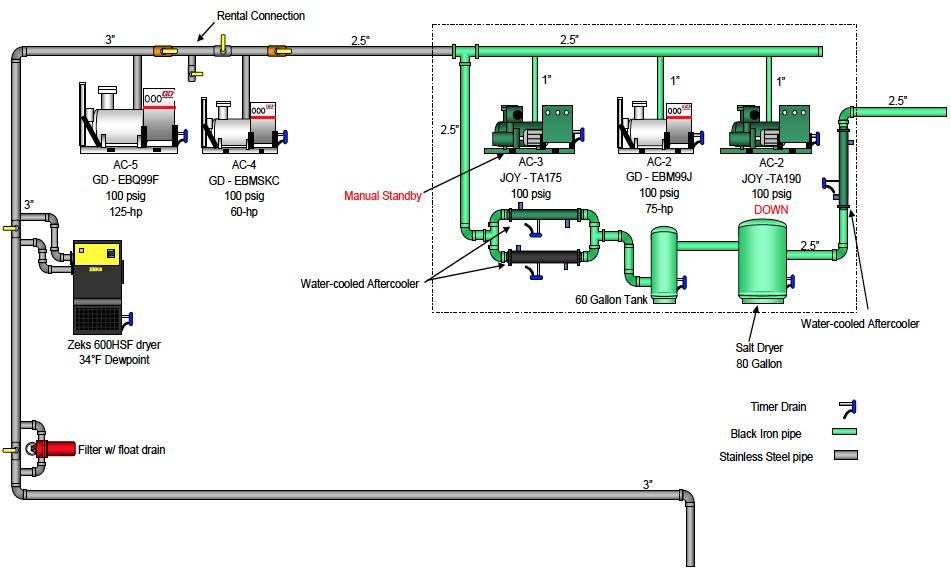
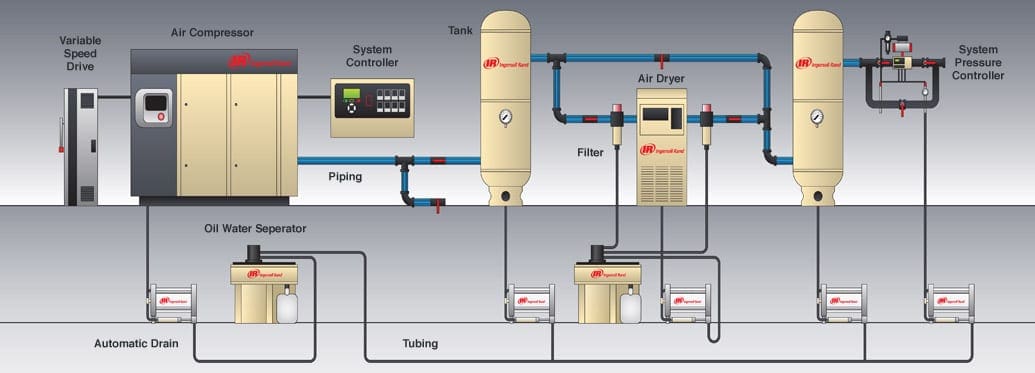
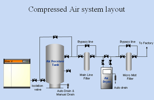
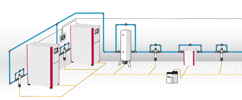
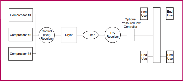
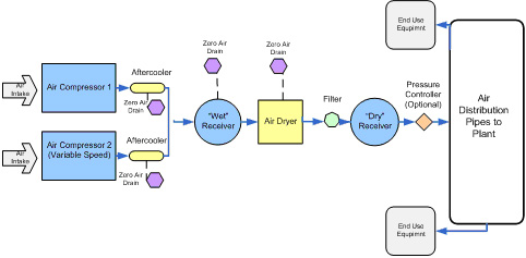
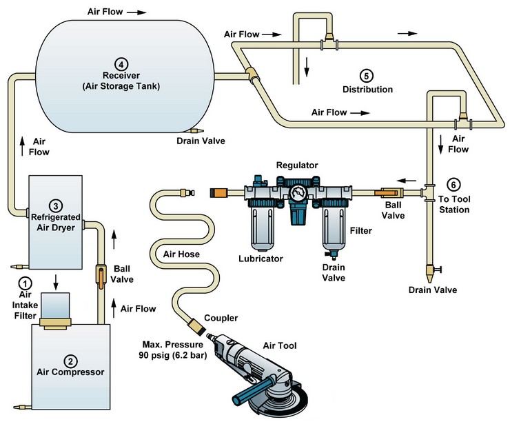
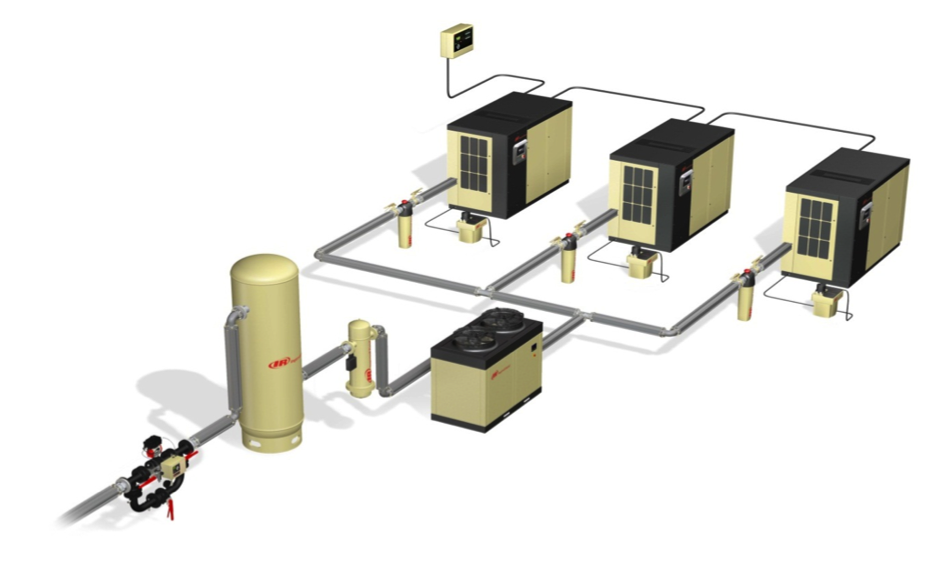
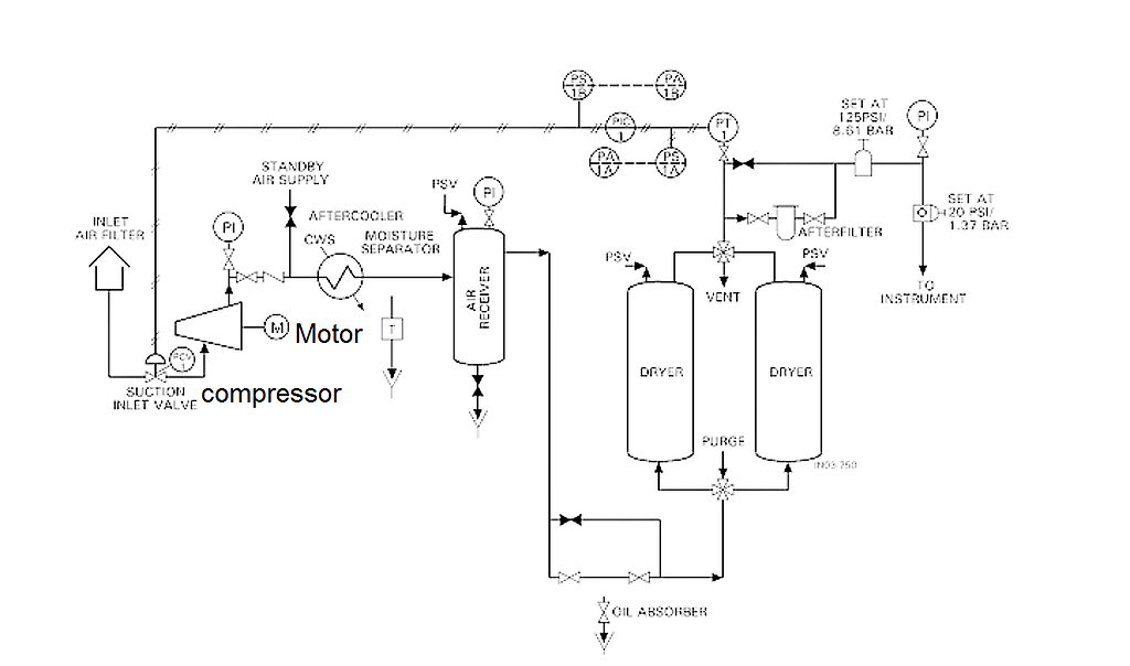
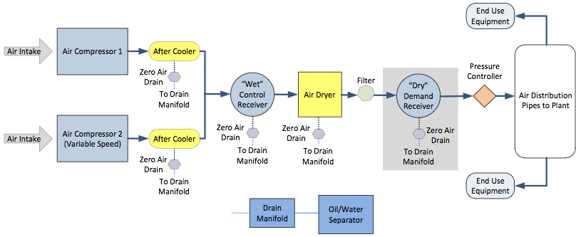
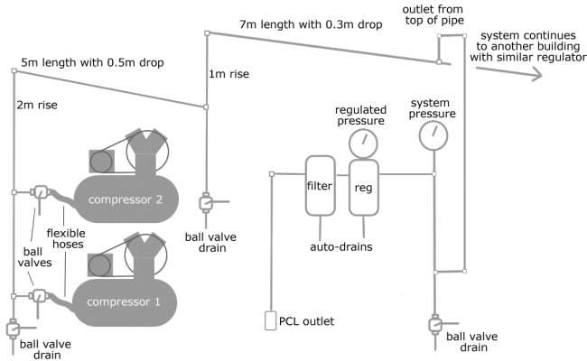
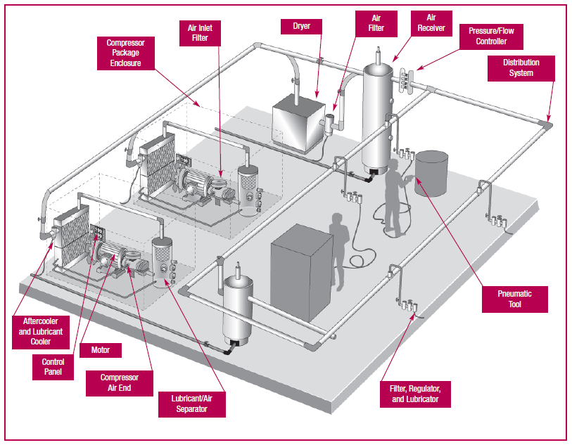
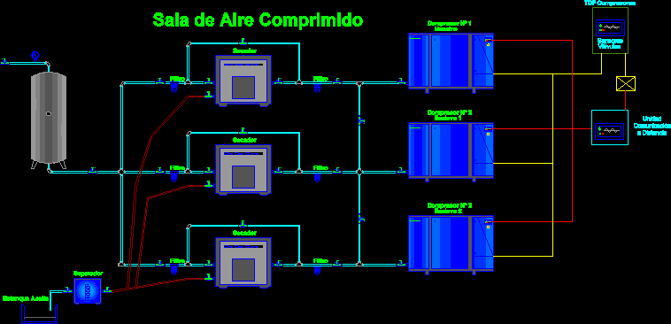
As shown in figure-1 instrument air supply system is typically comprised of filters compressors knock out drums aftercoolers intercoolers and air drying dehumidifying packages. Types of Compressors Air compressors in sizes 30 horsepower and below include both reciprocating and rotary compressors which compress air in different ways. Below is a typical example of an air compressor setup diagram.
14 The power flow inside a Typical Window air. When the tanks pressure reaches its engineered upper limit the air compressor shuts off. Construction of Air Suspension.
Major types of reciprocating compressors include reciprocating single acting reciprocating diaphragm and reciprocating rocking piston type. The compressed air can be used as energy as its released. The components of the air suspension system are.
Now compare the CFM number and the nearest length to the total length of the pipe and see where they interconnect on the chart. One of the most popular brands for Pex Plumbing is Rapid Air. Air compressor capacity rating is also stated in free-air volume.
Also you can find examples for the complete wiring diagrams for Window Air Conditioning Unit touch and remote control type in Fig7. Think of it like an open balloon.
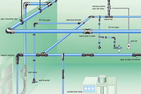
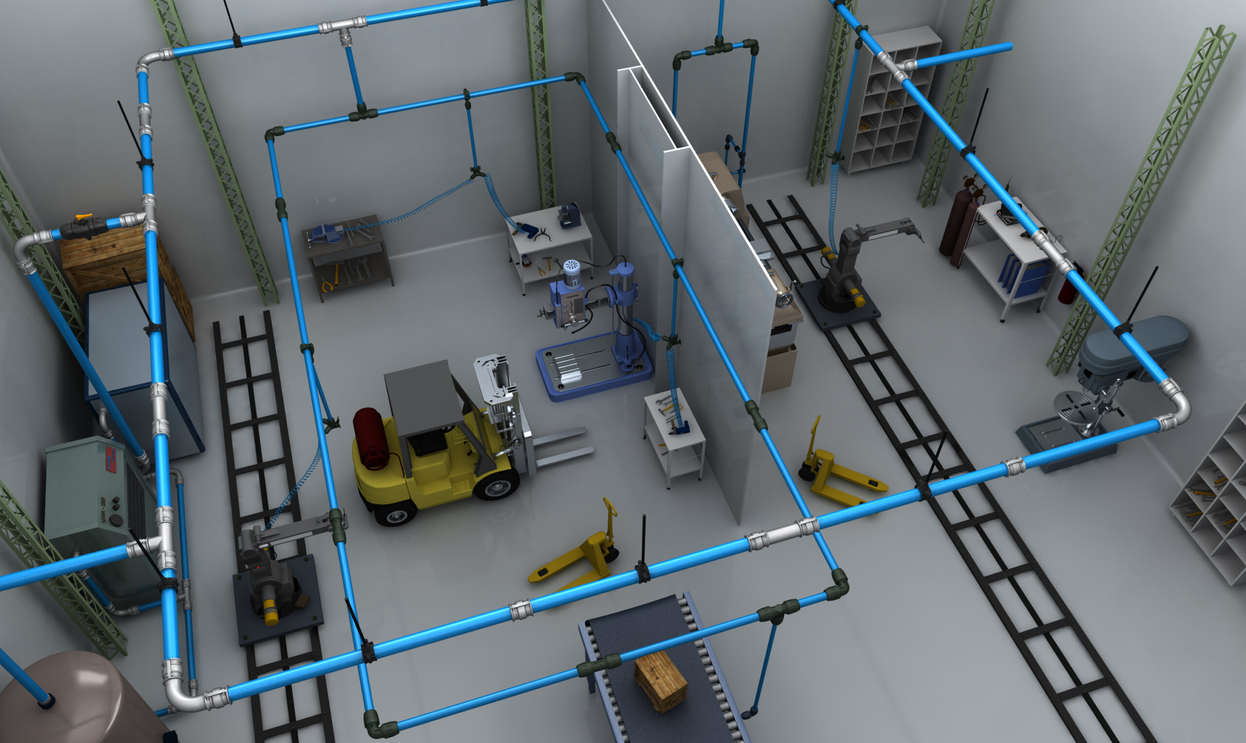
The risers transport the compressed air from the compressor plant to the consumption area.
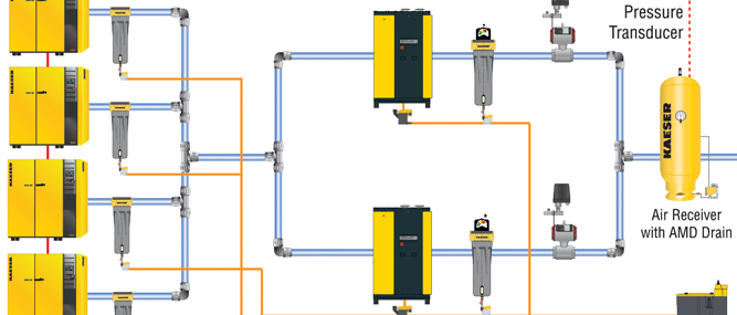
Air Compressor Maintenance Plan. Xas 1800 Cd7 Compressors Committed To Sustainable Productivity Ppt Online. Air suspension system Diagram Components Of Air Suspension System. To understand the operation of an air compressor let us assume the cycle and indicator diagram for a simple single stage reciprocating air compressor as shown below. The dryer should have a pre-filter and an after filter. The compressed air system is so vital that the facility cannot operate without it. Two 50 hp rotary compressors in a pharmaceutical plant packaging bay were operating at 115120 psig despite the 3 main air lines in the building and 80 psig pressure specification for the machines. Air compressors come in many di erent types and sizes. It consists of Air filter unloading valve Air compressor Air reservoir Brake valve and 4 numbers brake chamber.
The amount of atmospheric air compressed to a desired pressure required to operate the tool as designed. Fluid Power Equipment containing 113 elements of motors pumps. The components of the air suspension system are. And the receivers should be sized based on the CFM of the compressors. Construction of Air Suspension. In general they consist of an air pump a motor or engine and a tank to hold the compressed air. Click the image to enlarge The simple reciprocating air compressor has a piston which reciprocates inside the cylinder wall and cylinder head.















Posting Komentar untuk "Air Compressor System Diagram"